High-PrecisionTuning
Servo gain adjustment with one-touch ease
Advanced One-Touch Tuning Function

Servo gain adjustment is complete just by turning on the one-touch tuning function. With this function, machine resonance suppression
filter, advanced vibration suppression control II*, and robust filter are automatically adjusted to maximize your machine performance.
* The advanced vibration suppression control II automatically adjusts one frequency.

Suppress two types of low frequency vibrations at once
Advanced Vibration Suppression Control II


The advanced vibration suppression control II suppresses two types of low frequency vibrations owing to vibration suppression
algorithm which supports three-inertia system. This function is effective in suppressing residual vibration generated at the end of
an arm and in a machine, enabling a shorter settling time. Adjustment is easily performed on MR Configurator2.

Wide frequency range
Machine Resonance Suppression Filter

With advanced filter structure, applicable frequency range is
expanded to between 10 Hz and 4500 Hz. Additionally, the
number of simultaneously applicable filters is increased to
five, improving vibration suppression performance of a
machine.
High responsivity and stability
Robust Filter


Achieving both high responsivity and stability was difficult with
the conventional control in high-inertia systems with belts and
gears such as printing and packaging machines. Now, this
function enables the high responsivity and the stability at the
same time without adjustment. The robust filter gradually
reduces the fluctuation of torque in wide frequency range and
achieves more stability as compared to the prior model.

For Changes in Power Supply Environment
Reduce machine downtime
Large Capacity Main Circuit Capacitor

The capacity of main circuit capacitor is increased by 20% as
compared to the previous model, increasing the tolerance
against instantaneous power failure. The increased tolerance
reduces machine downtime and then improves productivity.
Wide power supply voltage input range
Compatible with 1-phase 200 to 240 V AC Input


Servo amplifiers of 2 kW or smaller are compatible with power
supply voltage of 1-phase 200 V AC to 240 V AC.
* When 1-phase 200 V AC to 240 V AC power supply is used with servo amplifiers of
1 kW and 2 kW, use the servo amplifiers with 75% or less of the effective load ratio.
The servo amplifiers of 1 kW and 2 kW cannot be mounted closely when 1-phase
power is input.
Reduce undervoltage alarms
Instantaneous Power Failure Tough Drive

When an instantaneous power failure is detected, this function
allows the servo amplifier to use the electric energy charged
in the main circuit capacitor in the servo amplifier to avoid an
alarm occurrence, increasing the machine availability even
with an unstable power supply.
A Variety of Positioning Functions
Easy to set a positioning data
Point Table Method
Setting position data (target position), servo motor speed, and acceleration/deceleration time constants in point table is as easy as
setting a parameter. Up to 31 points are settable for the point table. The positioning operation is performed with a start signal after
selecting the point table No.

Easy operation by program
Program Method*
Create positioning programs with dedicated commands. The positioning operation is performed with a start signal after selecting
the program No. The program method enables more complex positioning operation than the point table method. Maximum of 16
programs are settable. (The total number of steps of program: 480)

Easy to create electronic cam
Simple Cam Function
Various patterns of cam data* can be created easily by using MR Configurator2. Command pulse or point table/program start
signal can be used as input to the simple cam. The input command will be outputted to the servo motor according to the cam data.

* Cam curve can be selected from 12 types (constant speed/constant acceleration/5th curve/single hypotenuse/cycloid/distorted trapezoid/distorted sine/distorted constant speed/trapecloid/reverse trapecloid/double hypotenuse/reverse double hypotenuse). For details of simple cam function, refer to in the catalog.
Synchronous operation by encoder signal input
Encoder Following Function/Command Pulse Input Through Function
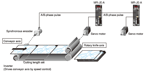
With the encoder following function, the servo amplifier receives A/B-phase output signal from the synchronous encoder as
command pulse, and the input command will be outputted to the servo motor according to the cam data. By setting cam data that
matches with sheet length, a diameter of the rotary knife axis, and synchronous section of the sheet; a system in which the
conveyor axis and the rotary knife axis are synchronized can be configured. Up to 4 Mpulses/s of input from synchronous encoder
is compatible with the servo amplifier.
The command pulse input through function allows the first axis to output A/B-phase pulse from the synchronous encoder to the
next axis, enabling a system the second and later axes are synchronized with the synchronous encoder.
Compensating a position gap by sensor input
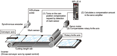
Mark Sensor Input Compensation Function
The actual position of the servo motor can be obtained based on the inputs from the sensor that detects the registration marks
printed on the high-speed moving film. The servo amplifier calculates compensation amounts and corrects position errors of the
rotary knife axis based on those inputs from the sensor so that the film can be cut at the set position.
Positioning Using Communication Function
Compatible with MODBUS® protocol
Communication Function (MODBUS® RTU)

In addition to RS-422 communication (Mitsubishi general-purpose AC servo protocol), RS-485
communication (MODBUS® RTU protocol) is supported.
MODBUS® RTU protocol is compatible with function code 03h (Read holding registers), etc.
Controlling and monitoring the servo amplifier by external devices is possible.
Compatible function code


While the point table is in operation, the next target position of
the point table can be overwritten.

While the point table is in operation, the position data is latched
by the mark detection function, and the current position latch
function let the controller to obtain the latched data.
Easy Monitoring and Maintenance
Analyze cause of alarm
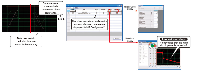
Large Capacity Drive Recorder


● Servo data such as motor current and position command before and after the alarm occurrence are stored in non-volatile
memory of the servo amplifier. Reading the servo data on MELSOFT MR Configurator2 helps you analyze the cause of the alarm.
● Check the waveform ((analog 16 bits x 7 channels + digital 8 channels) x 256 points) and the monitor values of 16 alarms in the
alarm history.
Reduce machine downtime incurred by age-related deterioration
Vibration Tough Drive 

Machine resonance suppression filter is automatically
readjusted when a change in machine resonance
frequency is detected by the servo amplifier. Losses
from the machine stop due to age-related deterioration
are reduced.
Support optimal maintenance of driving parts
Machine Diagnosis Function


This function detects changes of machine parts (ball screw, guide, bearing, belt, etc.) by analyzing machine friction, load moment of
inertia, unbalanced torque, and changes in vibration component from the data inside the servo amplifier, supporting timely maintenance
of the driving parts.

Easy troubleshooting
Three-Digit Alarm 

MR-JE series displays the alarm No. in three digits
to show the servo alarm in more details,
making troubleshooting easy.

User-Friendly Motors
Even in severe environment
Improved Environment Safety
HG-KN series and HG-SN series are rated IP65 and IP67
respectively.
* The shaft-through portion is excluded.
Cable leading in both ways
Selectable Cable Leading Direction
The power cable, the encoder cable, and the electromagnetic
brake cable are led out to either in direction of or in opposite
direction of the load side, depending on the selected
cables. (HG-KN series)
Setup Software
Preparation
Just follow the guidance, and setup is complete
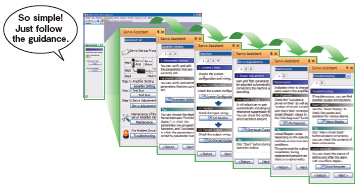
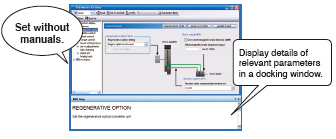
Servo Assistant Function

Complete setting up the servo amplifier just by following
guidance displays. Setting parameters and tuning are easy
since related functions are called up from shortcut buttons.
Supporting replacement from conventional system
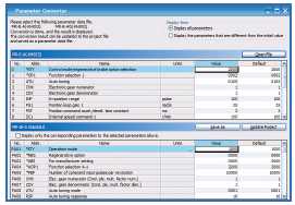
Parameter Converter Function
With this function, parameter files for MR-E series or MR-E
Super series are converted to those for MR-JE-A series.
Setting and Start-up
Easy and fast parameter setting
Parameter Setting Function

Display parameter setting in list or visual formats, and
set parameters by selecting from the drop down list. Set
in-position range in mechanical system unit (e.g. µm).
Parameter read/write time is approximately one tenth of the
conventional time.
Visible operation and power status
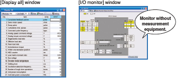
Monitor Function 

Monitor operation status on the [Display all] window. Check
power consumption without any measurement equipment
such as electric power meter, assign input/output signals,
and monitor ON/OFF status on the [I/O monitor] window.
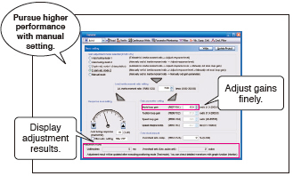
Servo Adjustment
Tuning is just one click away
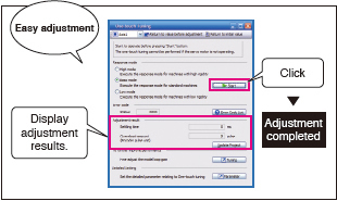
One-Touch Tuning Function 

Adjustments including estimating load to motor inertia ratio,
adjusting gain, and suppressing machine resonance are
automatically performed for the maximum servo performance
just by clicking the start button. Check the adjustment results
of settling time and overshoot.
Fine tuning of loop gain
Tuning Function 

Adjust control gain finely on the [Tuning] window manually
for further performance after the one-touch tuning.
Convenient with overwrite and graph history functions
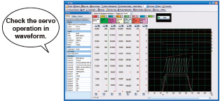
Graph Function 

The number of measurement channels is increased to 7 channels
for analog, and 8 channels for digital. Display various servo
statuses in the waveform at one measurement, supporting setting
and adjustment. Convenient functions such as [Overwrite] for
overwriting multiple data and [Graph history] for displaying graph
history are available.
Analyze the frequency characteristics
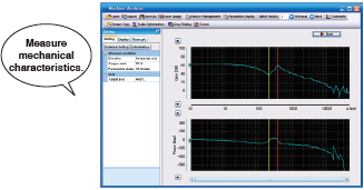
Machine Analyzer Function 

Input random torque to the servo motor automatically and
analyze frequency characteristics (0.1 Hz to 4.5 kHz) of a
machine system just by clicking the [Start] button. This
function supports setting of machine resonance suppression
filter, etc.
Maintenance
For timely parts replacement
Servo Amplifier Life Diagnosis Function 

Check cumulative operation time and on/off times of inrush relay. This
function provides an indication of replacement time for servo amplifier
parts such as capacitor and relays.
Find out the aging deterioration of machines
Machine Diagnosis Function 


This function estimates and displays machine friction and
vibration in normal operation without any special measurement.
Comparing the data of the first operation and after years of operation helps to find out the aging deterioration of a
machine and is beneficial for preventive maintenance.